![[Back To Home Page]](home.gif)
![[About?]](about.gif)
![[Email
Us]](email.gif)
 Pictures of the SBEDAR system!
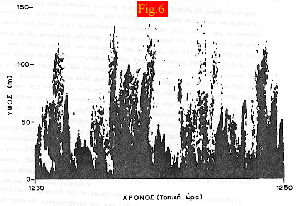
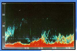
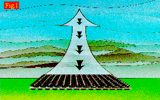 An acoustic radar is a device acting as the well known radars, with the
difference that the transmitted and the received signals have frequencies
in the acoustic region. An alternate name for this class of instruments is
'Sodar', due to the SOund Detection And Ranging'. A short acoustic pulse is transmitted in the atmosphere.
While it is travelling in there, it is scattered from the atmospheric
irregularities. Here, the irregularities don't mean a 'target' object, as in the
usual electromagnetic or microwave radars. A change in the wind velocity, a
turbulent layer, a temperature inversion e.t.c. cause scattering of the acoustic
waves. A part of the scattered signal returns to the receiver, where it is
collected and processed.
An acoustic radar is a device acting as the well known radars, with the
difference that the transmitted and the received signals have frequencies
in the acoustic region. An alternate name for this class of instruments is
'Sodar', due to the SOund Detection And Ranging'. A short acoustic pulse is transmitted in the atmosphere.
While it is travelling in there, it is scattered from the atmospheric
irregularities. Here, the irregularities don't mean a 'target' object, as in the
usual electromagnetic or microwave radars. A change in the wind velocity, a
turbulent layer, a temperature inversion e.t.c. cause scattering of the acoustic
waves. A part of the scattered signal returns to the receiver, where it is
collected and processed.There are various configurations for a sodar device. |
These systems use the same antenna for transmitting the acoustic pulse and receiving the backscattered acoustic waves. These systems use two antennas, one for trasmission of the acoustic pulses and one for the reception of the signals scattered to the direction the receiving antenna points to. |
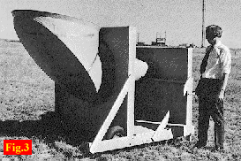
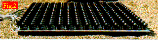
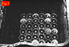 An important point in the evolution of the sodars was the usage of array antennas. An antenna constructed from Celestions acoustic transducers, in a square planar topology, is presented in the figure left. You can also see in this figure the screening of the antenna using sound absorbing material. The screening is used to supress the sidelobes of the antenna (i.e. to reduce the undesired signal received from the sidelobes).
|
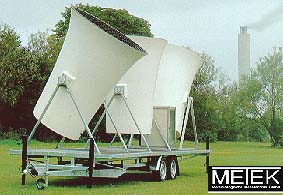 Example of the antenna of a modern tristatic sodar (METEK's MODOS Model).
|
 Example of a modern antenna of a phased array sodar (REMTECH's PA2 Model). Due to the number of elements used and electronic 'apodization' (sidelobe suppression through the usage of different amplitudes for the signals feeding the elements) of the beam, the resulting main lobe's directivity and sidelobe levels are excellent and there is no need for shielding the antenna.
|
|
Some examples of the Operating software, developed to control the system's setup and operation, in a Menu Driven - User friendly mode, may be found here.
Some photos of the SBEDAR System, may be found Here!!